| Sinclair QL Service Manual | ||
|---|---|---|
| Previous | Next | |
1.1 The use of the following test procedure is strongly recommended after carrying out unit repairs, thus ensuring that a once defective unit is completely operational before return to the owner. The procedures can also be used effectively during fault diagnosis (Section 4).
1.2 Adjustments. The pre-Issue 6 QLs have a trimming capacitor TCI associated with the real time clock. It is factory-set to give a clock frequency of 32.768 kHz at IC23 pins 30 and 31 and should not require further adjustment.
2.1 The system test is conducted with the QL connected to a colour monitor and a domestic colour TV receiver so checking both display paths. Additional test equipment is required as follows:
2.2 With the QL powered-up and the test software loaded and running, the test progresses through 9 well-defined states during which each of the QL's functions is exercised. Some stages require the operator to respond to prompts displayed on the TV/monitor, others run autonomously outputting only a test 'passed' or 'failed' message. At the end of system test the message QL TEST COMPLETE is displayed.
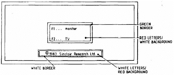
3.1.1 Connect the QL and power-up as if for normal use; check that the yellow 'power on' LED is illuminated and the following message is displayed on both screens:
3.1.2 Connect the RS232 loopback cable, connect the joysticks to the QL's CTL1 and CTL2 sockets, insert the system 2 test cartridge in microdrive 1 (MDV1) and press the F2 key. Check that the microdrive 1 LED lights up when the drive is running.
3.1.3 At some stage during program loading a title page is displayed briefly. A short time later two bleeps are heard and a message is displayed requesting a blank cartridge to be placed in MDV2.
3.1.4 Insert a blank tape cartridge into MDV2 as requested.
3.2.1 After the message to load a blank cartridge into MDV2 is displayed, both screens should clear and then display the following colour test card.
NOTE: On each colour bar the word 'Test' should be written 8 times, once in each of the following colours from top to bottom Black - Blue - Red - Magenta - Green - Cyan - Yellow - White
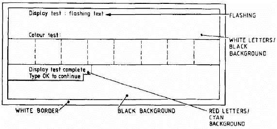
3.2.2 Check that the colours on the monitor are the same as those on the TV; check that the flashing text is satisfactory; type OK to proceed.
3.3.1 Check that the following is displayed:
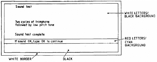
3.3.2 After hearing two cycles of trimphone followed by the low pitch tone, type OK to continue.
3.4.1 Check that the following is momentarily displayed:
Network test : OK
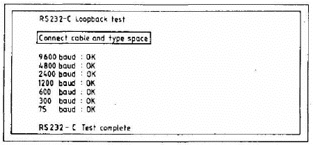
3.5.1 Check that the following is displayed:
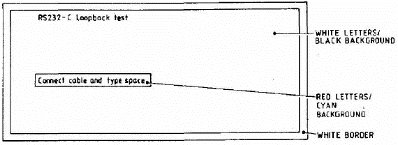
3.5.2 Connect the loopback cable in the QL's SER1 and SER2 sockets and press the space bar; the following message should be temporarily displayed:
3.6.1 Check that the following is displayed:
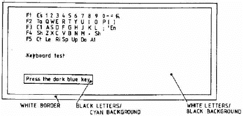
3.6.2 Press the key indicated by a dark blue background on the display. The blue background should be replaced by green and move onto the next key. Press all keys in sequence and note that on pressing the ALT key the message: 'keyboard test complete' is displayed momentarily.
NOTE: Each key should be pressed individually, NOT skimmed over. If keys have a tendency to stick, the cause should be investigated.
3.7.1 Check that the following is displayed:
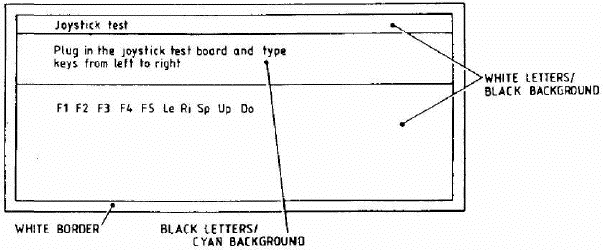
3.7.2 Ignore the message concerning the joystick test board (intended for factory use only). Instead press the F1, F2, F3, F4 and F5 keys on the keyboard followed by the Left, Right, Space, Up and Down keys on the keyboard. The background colour of each key on the display should change from blue to green as in the keyboard test. On pressing the last key the message 'joystick test complete' is displayed momentarily.
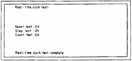
3.8.1 Check that the following are displayed momentarily:
3.9.1 Check that the following message is displayed and that MDV2 starts to run and the corresponding red LED is illuminated.
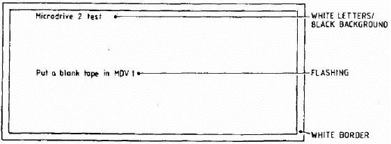
3.9.2 Insert a blank cartridge in MDV1.
3.9.3 After a short delay the following message should be displayed:
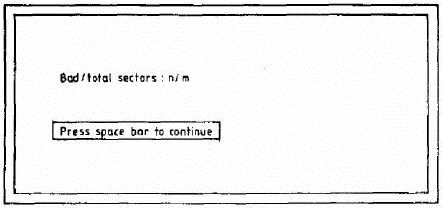
NOTE: On pressing the space bar two bleeps should be heard and the following message displayed in green:
Microdrive 2 test OK
3.10.1 As microdrive 2 test (para 3.9).
3.11.1 If during either microdrive test, the cartridge is not inserted correctly the following message is displayed in red:
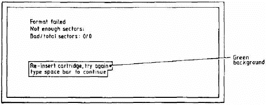
3.11.2 Re-insert the cartridge in MDV1 or MDV2 as appropriate and press the space bar. If the test fails a second time the following message is displayed:
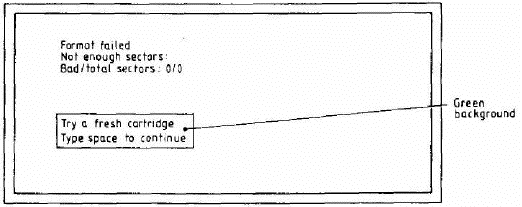
3.11.3 Insert a new cartridge in MDV1 or MDV2 as appropriate and press the space bar. If the test fails again the message in para 3.11.1 is repeated; re-insert the cartridge and press the space bar.
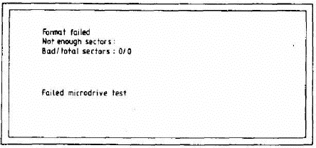
3.11.4 If the test fails a fourth time, the following message is displayed and the test is abandoned.
3.12.1 On satisfactory completion of Microdrive 1 Test the following message should be displayed on green:
QL TEST COMPLETE
3.12.2 Press the RESET pushbutton and check that the display is as shown in para 3.1.1.
| Previous | Contents | Next |
| Disassembly/Assembly | Fault Diagnosis and Repair |